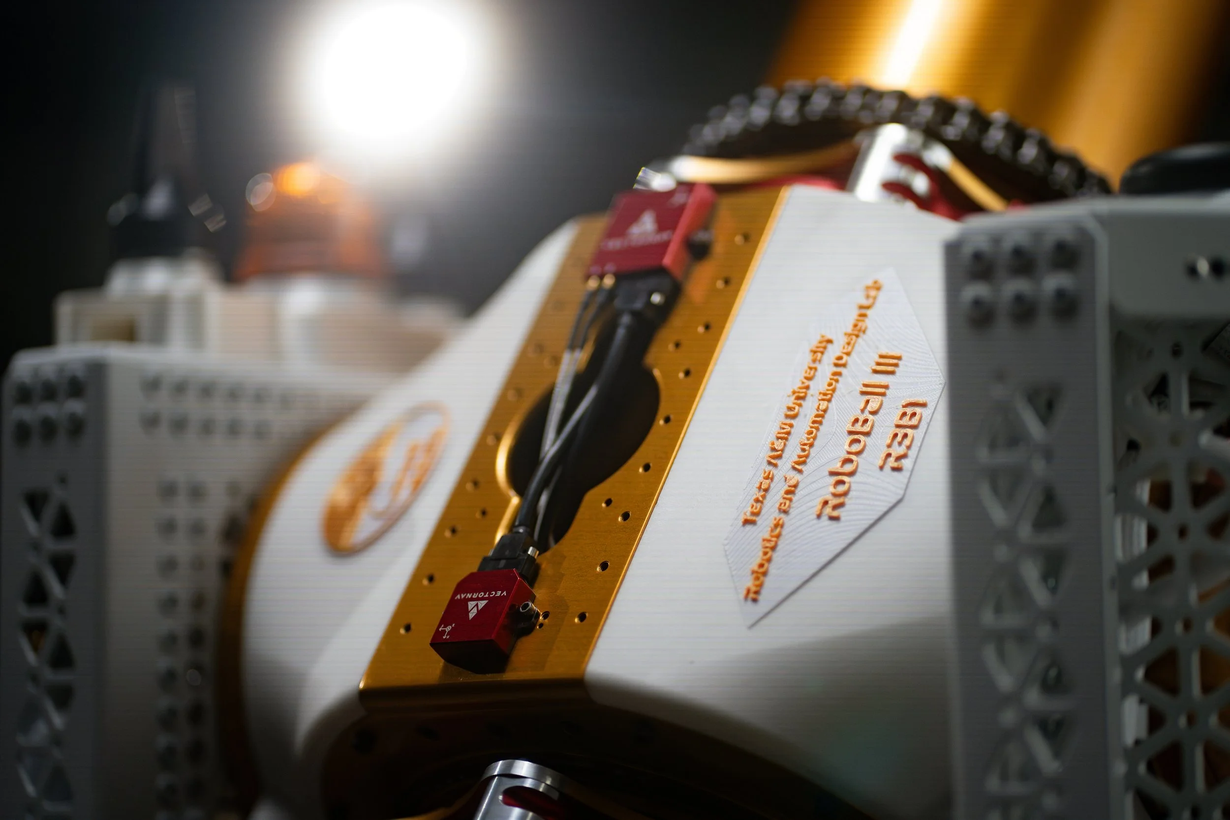
RoboBall Pendulum Design
Operating Principles
RoboBall has a two degree-of-freedom pendulum that it uses to move. In essence, the robot drives where it points the pendulum. The location of the center of gravity and the mass of the pendulum is a critical design parameter, as it governs the torque, slope-climb ability, and off-road capability of the vehicle.
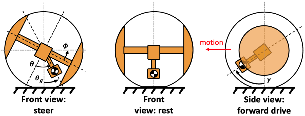
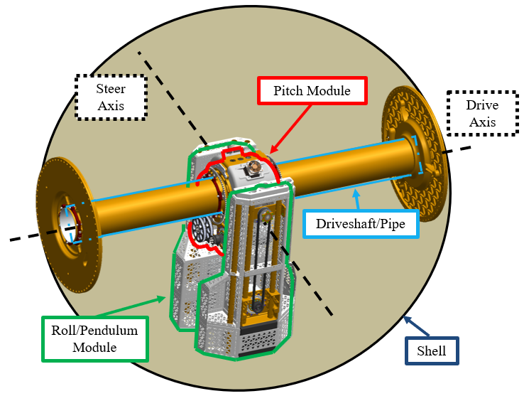
Freedom in placement of this CG is constrained by a mass budget, available volume, actuators, and torque/speed requirements. The pitch module (red) is the main drive mechanism of the robot. The roll module (green) is what the robot tilts to steer.
Models
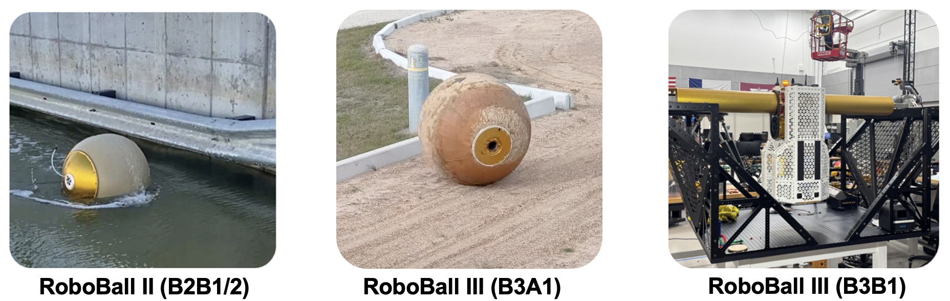
I’ve worked on 3 versions of RoboBall:
RoboBall II B2B1: a 2ft diameter software/controls testbed.
RoboBall III B3A1: Gen 1 of the 6ft diameter, 350 lb mission-capable RoboBall III.
RoboBall III B3B1: Gen 2, 6ft, 450 lb RoboBall III designed to have superior mobility and robustness to Gen 1.
RoboBall III Drivetrain Redesign
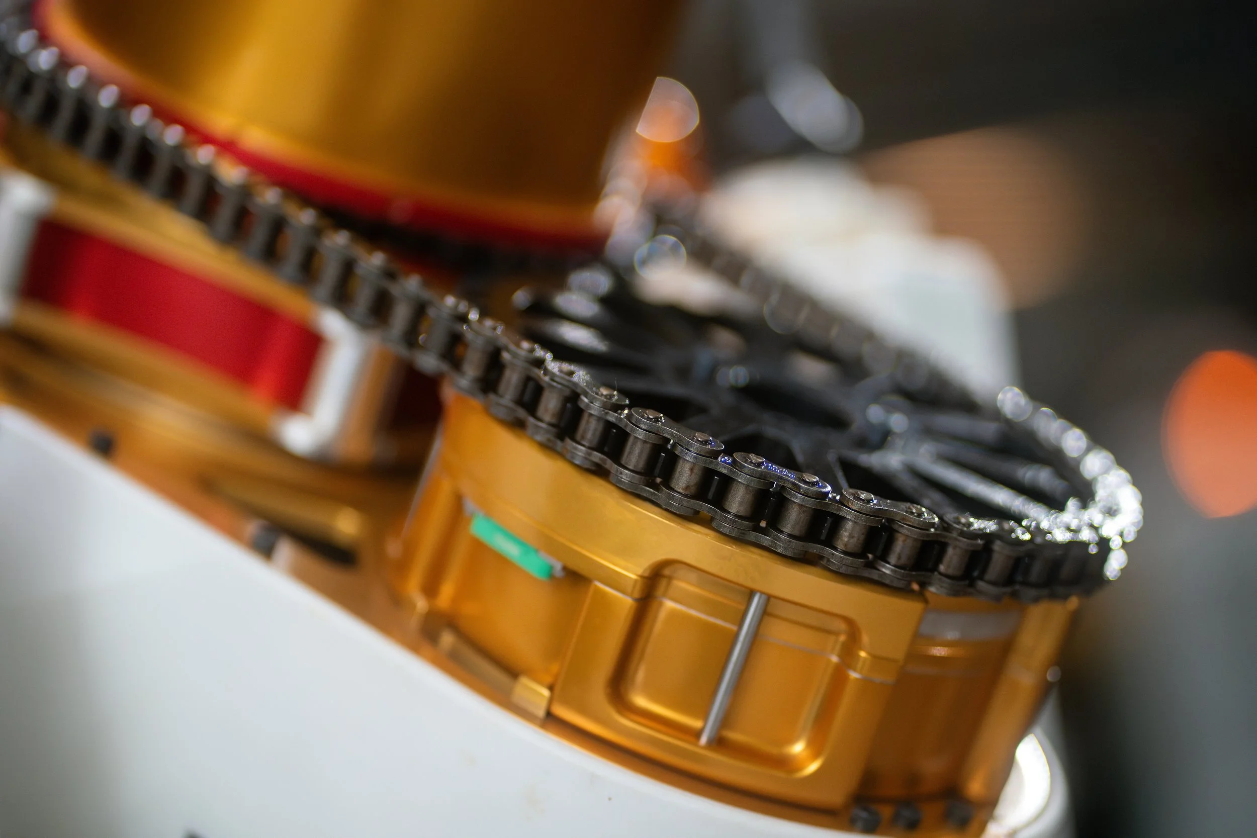
I led the redesign of the pitch drivetrain for RoboBall III Gen 2 (B3B1). Gen 1 could only climb a max slope of 9 degrees as a result of its low torque and radially-small CG, which also limited off road mobility. Mechanical complexity in the Gen 1 drivetrain, which used a 2-stage belt-#35 chain reduction that proved to be unreliable and break under heavy dynamic loads.
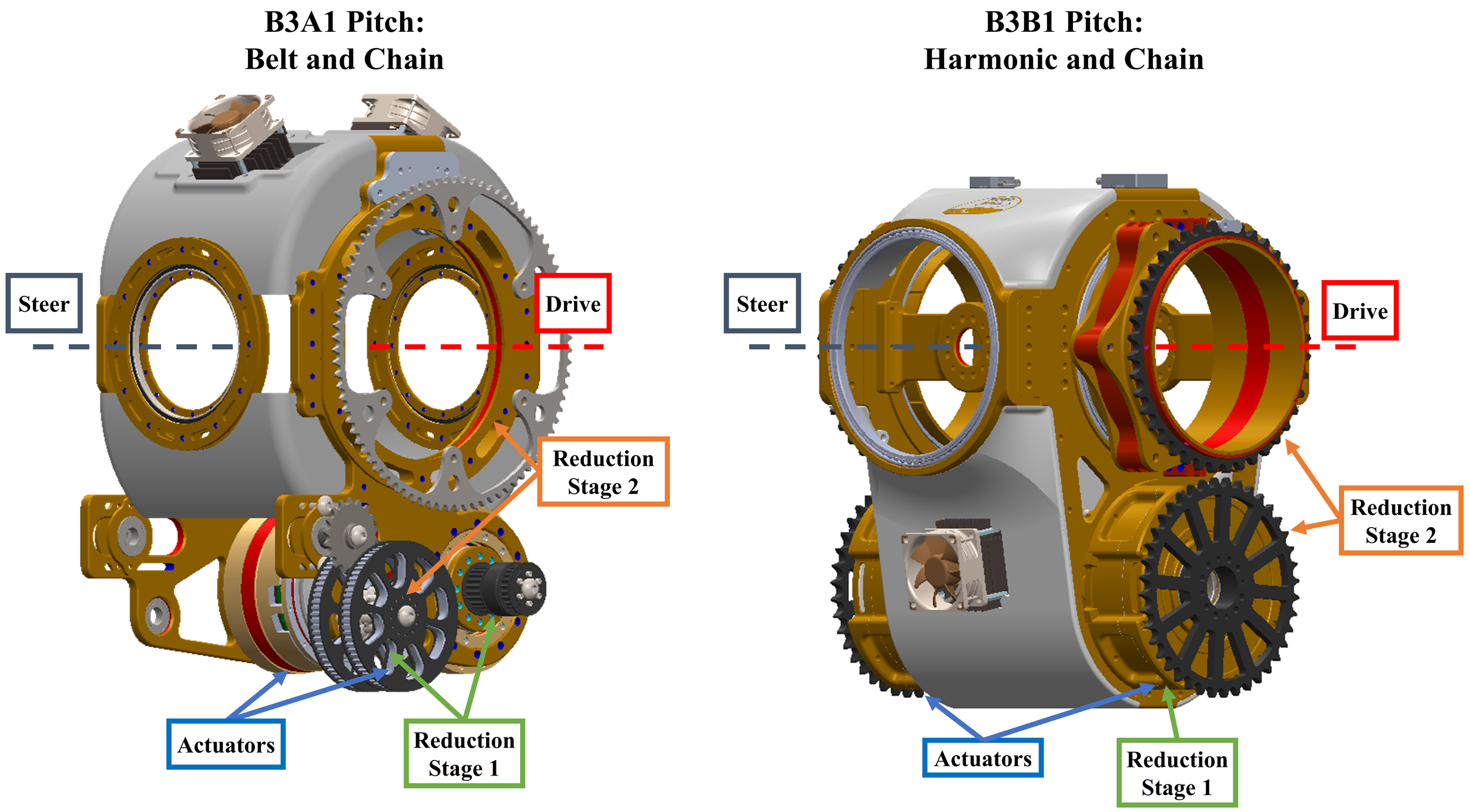
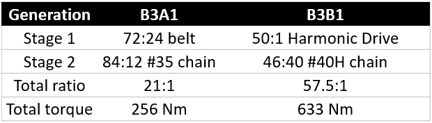
To increase the mobility of Gen 2, I derived the required CG location and mass budget to increase the slope-climb from 16% (9 deg.) to 35% (19 deg.). I utilized Gen 1B actuators designed by the in-house actuator team, which had integrated Harmonic Drives within the actuator, with a larger #40H chain to maximize robustness and prevent thrown chains. The overall structure was also made with design-for-maintenance principles in mind, reducing service time from 6-8 hours with multiple people on Gen 1 to less than 10 minutes with one person on Gen 2.
The actuator reductions, chain size, and sprocket reductions were all parametrically designed to support the gravitational torque increase of the pendulum while maintaining a factor-of-safety that could survive unpredictable dynamic loading.
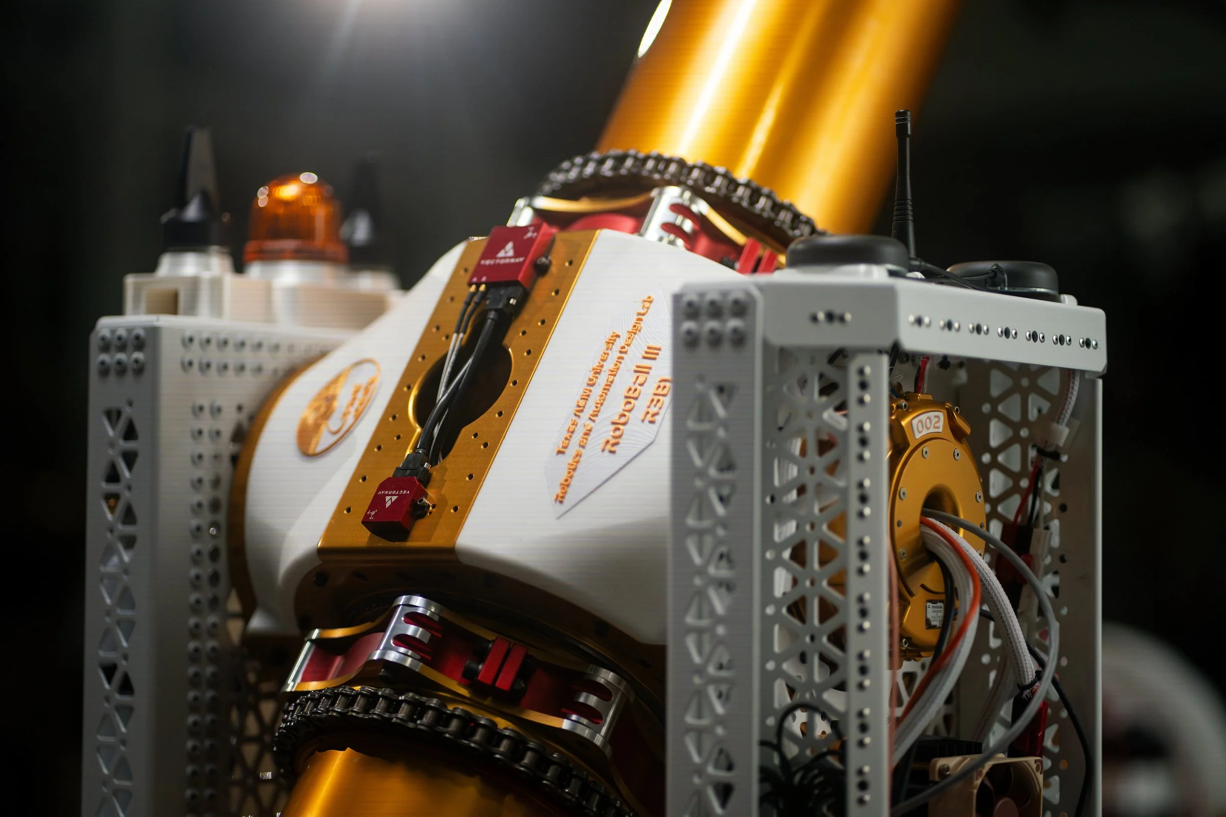
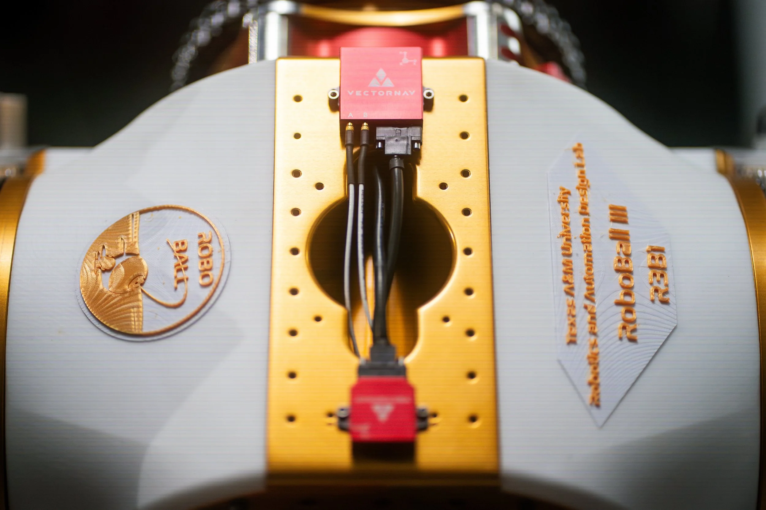
While redesigning pitch, I also redesigned the roll assembly to hold 2x the battery capacity (now around 2 kWh) and move the CG almost 50% further out (7.7 in to 11.4 in). Access to key electronics like motor controllers, communication routers, and intelligence was also made easier.
From Design to Hardware in 4 Months
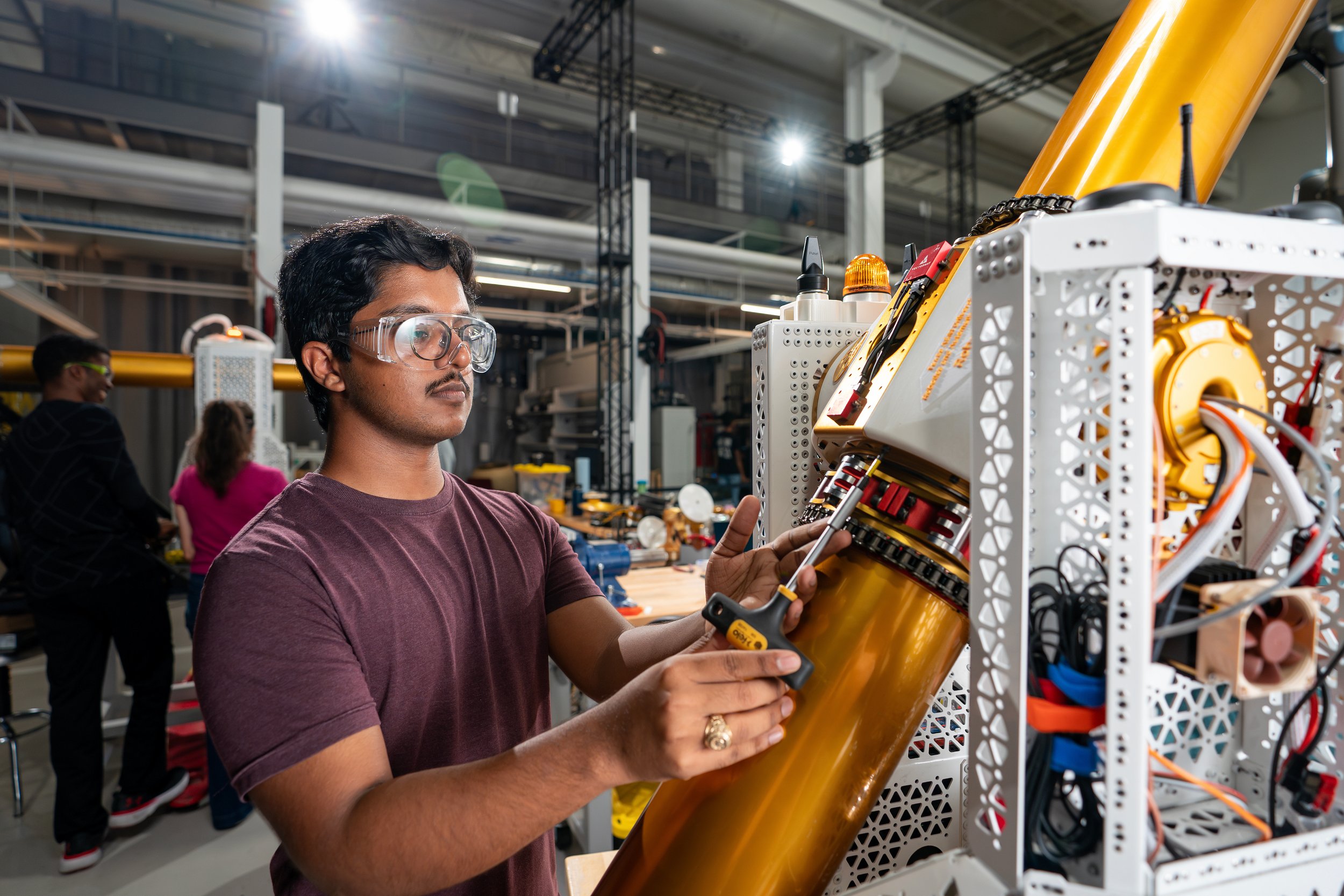
I owned fabrication and assembly for Gen 2, coordinating CNC machining across in-house shops and external vendors. When lead times on the thin-section A-bearings slipped, I altered bearing capture to temporarily use substitute bearings, keeping the build on schedule. Gen 1 took 12 months from preliminary design to functional prototype. Gen 2 did it in 4 months.
Validation
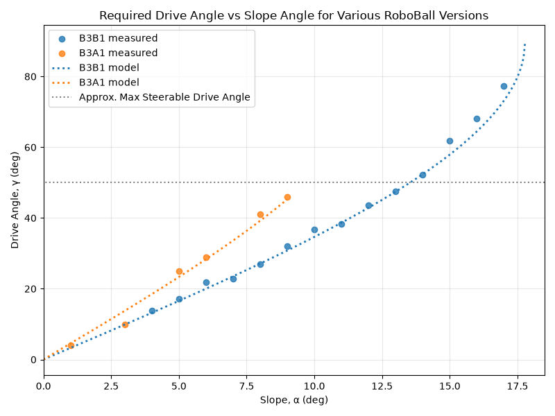
Gen 2 climbs a 17 degree slope, slightly short of the 19 degree target. The limit is control sensitivity as the pendulum approaches level with the ground and required lifting torque decreases, so the gap is a controls problem rather than a mechanical one. The drivetrain mechanically supports an 18.5 degree slope climb.
This is still nearly double Gen 1’s capability with a slope-climb increase from 9 deg. (16%) to 17 deg. (31%). The redesigned drivetrain also survives dynamic maneuvers that broke Gen 1’s hardware. It also enables motions that Gen 1 couldn’t perform at all, like full rotations about the drive axis, allowing the nearly 500 lb robot to jump (seen below).
The slightly more efficient drivetrain combined with the Roll assembly changes, such as doubling the battery capacity, also led to an increase in max driving range from 22.8 miles to 47.9 miles, further promoting RoboBall as a viable extraterrestrial explorer.