RoboBall III Shell Design
RoboBall’s Soft Shell
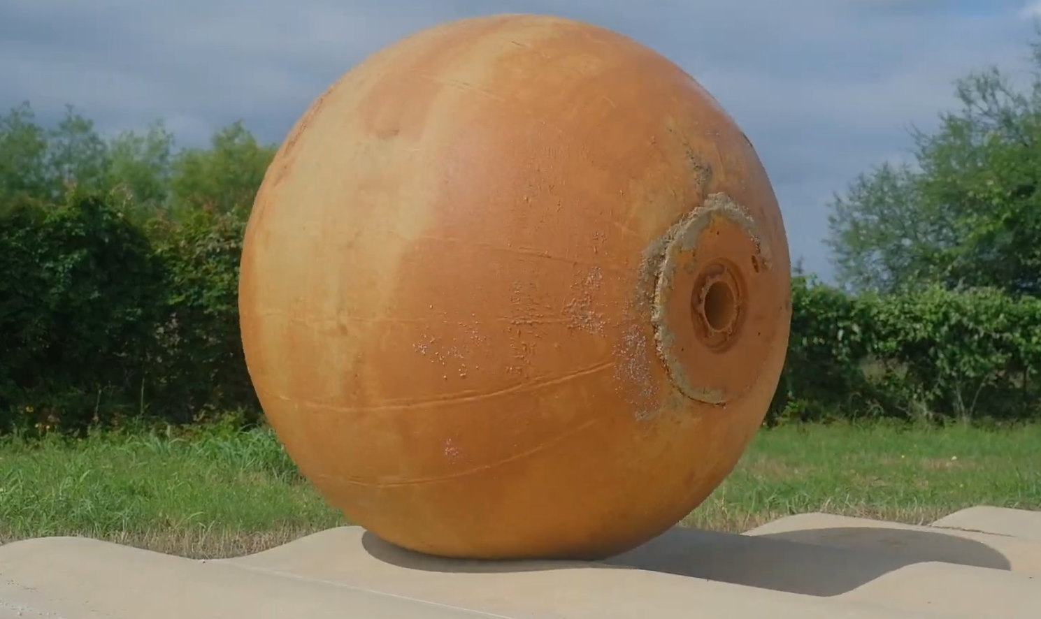
RoboBall’s soft outer shell is one of its most defining features, particularly at the scale of RoboBall III (6ft diameter). It provides environmental isolation and impact resistance for the robot, essentially acting as an omni-directional suspension.
Sphericity of these shells is critical and significantly governs the robots control authority.
I was the primary designer of all the shells for RoboBall III.
Shell Spray Forming
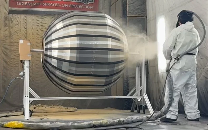
RoboBall shells are made using spray-forming with a military-grade two-part elastomer on a deconstructable mold. This mold was deliberately undersized so that once the polymer expanded during inflation, the final shell would be spherical.
I designed and built the shell manufacturing process for RoboBall III, including the mold, rotary stand, and actuation, while communicating with an external vendor (Rhino Linings) for the polymer.
Previously, there was no accurate way for us to predict the polymer shell’s expansion due to a lack of knowledge of the material properties and viable models. As such, parameters like the reduction had to be determined empirically, which was extremely costly.
The Importance of Sphericity
I produced 3 shells in this empirical process.
Shell A: The first shell tried to scale linearly from RoboBall II, but was too thin and had an anisotropic thickness, resulting in non-spherical geometry.
Shell B: This shell introduced thickness homogeneity, but the resulting thicker shell due to manufacturing limitations expanded less than intended, producing a cylindrical shape.
Shell C: The final version of the RoboBall III shell maintained the thickness homogeneity of Shell B while producing a spherical shape.
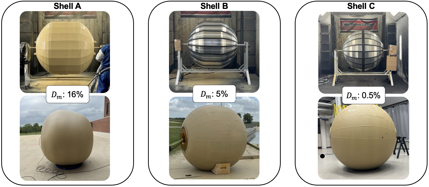
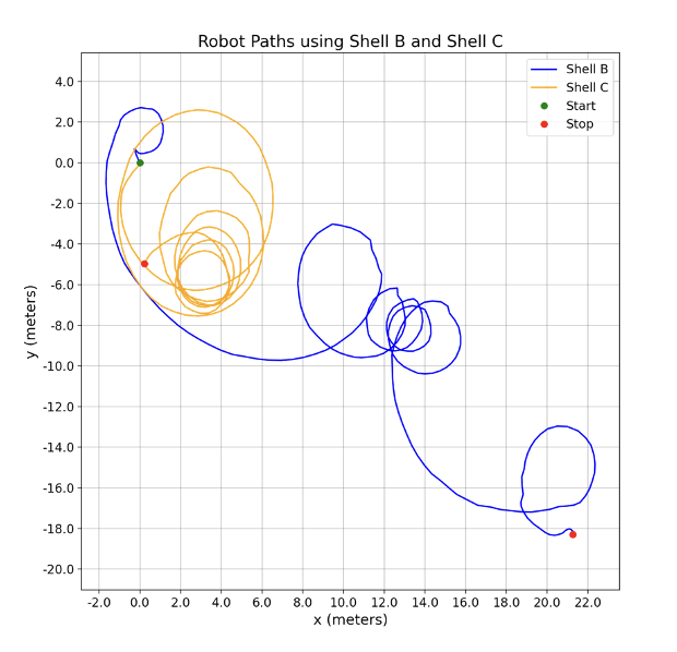
I quantitatively evaluated the effects of the shell geometry through sphericity, contact geometry, passive steering response, active pendulum control effort, and robot agility in Shell B and C (Shell A was too thin to survive very long). Shell C outperforms Shell B in all regards, including requiring no feedforward geometric compensation in the steer controller to maneuver. This produces a more predictable response from the full system, making it more controllable and usable in open-loop navigation.
Robot paths at a constant drive velocity and constant steer setpoint.
This empirical shell design was expensive, however. Each shell prototype cost $10k-15k and weeks of setup/setdown time. We needed to be able to analytically predict how to size a mold to produce a spherical shell, regardless of radius.
Shell Modeling
Model Refinement
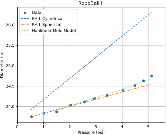
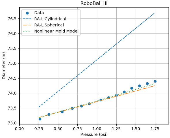
The first models predicting shell expansion iterated through cylindrical to spherical geometry using the thin-walled pressure vessel stress-strain equations. These equations bracketed the actual expansion data in the full robot system.
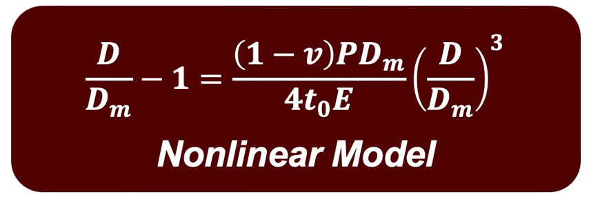
To better predict expansion and design the mold, I derived a nonlinear incompressibility-corrected expansion formula which accounted for the increasing stress as the shell expanded and thinned. This formula could be used with load-informed material properties to size a mold for any desired radius, or used to predict expansion for an already manufactured shell.
This was used by the team to accurately size a new radius of RoboBall on the first try, reducing the cost of building a shell from $40k to $5k.
Material Modeling
The polymer we were using (Rhino Linings Battlejacket) was initially developed as vehicle armor and had no published stress-strain data. Designing the shell effectively required an understanding of the material properties.
Initially, I tensile-tested the polymer per ASTM D412 standards. This protocol does not account for load-influenced changes in material properties, and rather produces a load-agnostic Young’s modulus, however, and I observed that this modulus was too high to be representative of the material in operation.
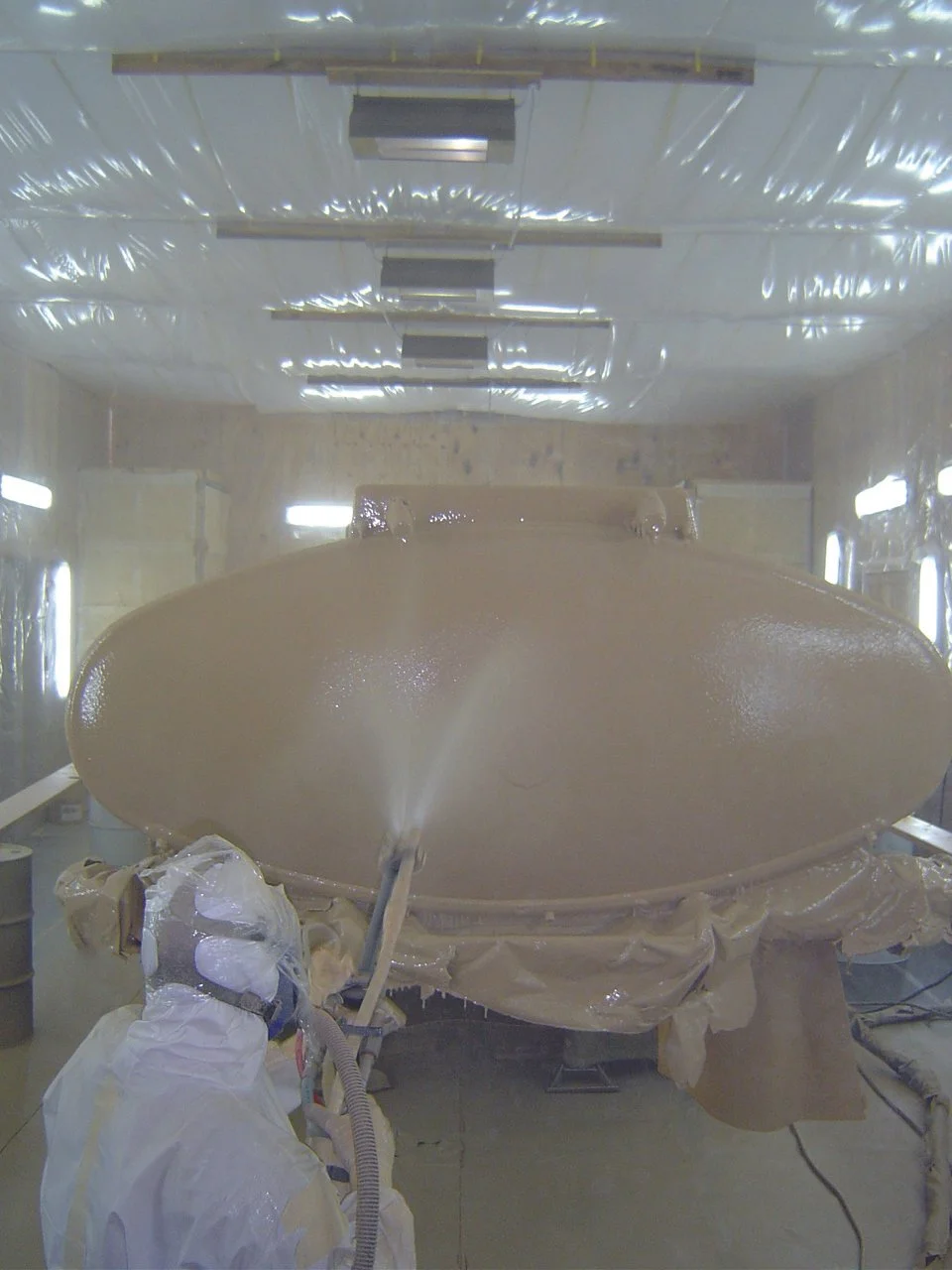
Rhino Linings Battlejacket on a truck.
Image source: Rhino Linings
I examined the load influenced material properties of the polymer. I did so using same-batch, controlled-temperature, dead-hang test fixtures representing the same stress as that in the robot shell.
Does the polymer change after each use?
Known as the Mullin’s effect, I quantified the early-load-cycle softening of the material due to stress and found that the effective stable modulus is only 56% of the D412 measured modulus. This value, when used in my nonlinear expansion model, predicted the geometry of RoboBall II (2ft) and RoboBall III (6ft) across their pressure range with correlation coefficient of 0.99 and 0.991 respectively.
Is the polymer affected by mechanical cycling?
I tested the polymer in purely bending (no axial load) using a cam-slider test jig, simulating the contact patch of the ball moving across the surface of the shell as the robot drove. Using preconditioned samples to prevent confounding effects, I tested material properties after each simulated mile of driving, and found no meaningful changes in the elasticity of the polymer.
Does the polymer change over time?
I evaluated creep in the polymer, and found that while it does creep significantly in a uniaxial test, in equibiaxial loading (like in the robot’s shell), the creep rate in the diameter is negligible. I justified this by calculating the deviatoric stress along each axis and using an estimated creep flow law, which confirmed this behavior.